Call or Text: +1 (208) 425-2990
Email: Sales@DroneSprayPro.com

Best Overlap for High-Resolution Field Surveys
I’d start with 80% front overlap and 70% side overlap for a standard RGB field survey. For dense canopy, repetitive rows, or uneven ground, I’d test higher overlap before flying the whole field.
But more overlap doesn’t mean sharper images - or a more accurate map. Here’s what I’d check:
- Resolution: Set your target GSD first. For example, 0.5 inch per pixel is about 1.3 centimeters per pixel.
- Flight plan: Match altitude, line spacing, photo timing, and flight direction to the crop, terrain, and wind.
- Image quality: Check focus, exposure, and blur. Use sensor-specific settings for multispectral work.
- Flight limits: Check clearance, weather, batteries, and FAA rules.
- Results: Fly a short test, inspect coverage and alignment, and measure accuracy with independent checkpoints.
My rule: <u>test before scaling up</u>. I’d lower overlap only after the test shows complete coverage and clean image matching - and keep the flight records with the finished map.
Understanding Overlaps in Drone Mapping
sbb-itb-3b7eef7
Overlap Settings for Different Field Conditions
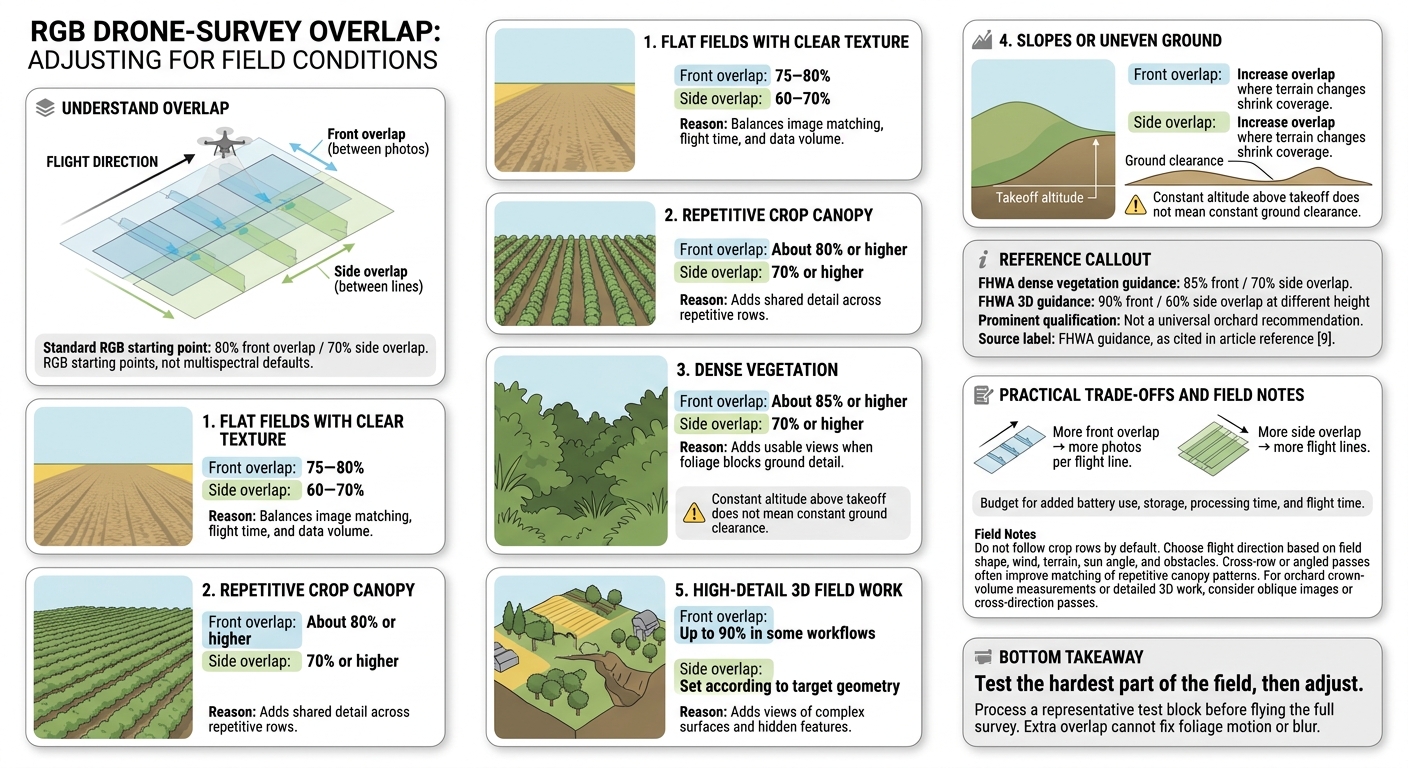
Drone Survey Overlap by Field Condition
After setting baseline overlap, use field texture and terrain to choose your starting settings. The values below are RGB starting points, not multispectral defaults. Test the hardest part of the field, then adjust.
| Field condition | Front overlap | Side overlap | Reason for the setting |
|---|---|---|---|
| Flat fields with clear texture | 75–80% | 60–70% | Balances image matching, flight time, and data volume. |
| Repetitive crop canopy | About 80% or higher | 70% or higher | Adds shared detail across repetitive rows. |
| Dense vegetation | About 85% or higher | 70% or higher | Adds usable views when foliage blocks ground detail. |
| Slopes or uneven ground | Increase overlap where terrain changes shrink coverage. | Increase overlap where terrain changes shrink coverage. | Maintains coverage as ground clearance and image footprint change. |
| High-detail 3D field work | Up to 90% in some workflows | Set according to target geometry | Adds views of complex surfaces and hidden features. |
The Federal Highway Administration (FHWA) lists 85% front and 70% side overlap for dense vegetation. Its 3D guidance lists 90% front and 60% side overlap at different height levels for structures such as towers and buildings. That is not a universal orchard recommendation. These references support higher overlap for difficult targets, but you still need to test the final settings in the field.[7]
More front overlap means more photos per flight line. More side overlap means more flight lines. Budget for added battery use, storage, processing time, and flight time.[7]
Flight Planning for Row Crops and Orchards
In row crops and orchards, flight direction matters as much as overlap. Do not follow crop rows by default. Choose your direction based on field shape, wind, terrain, sun angle, and obstacles.
Cross-row or angled passes often provide better texture for matching repetitive canopy patterns. But you still need steady speed, safe clearance, and enough side overlap. For orchard crown-volume measurements or detailed 3D work, consider oblique images or cross-direction passes. Downward-facing images can miss crown sides and hidden areas. Process a representative test block before flying the full survey.
How Slopes and Wind Affect Overlap
Uneven ground and wind can change actual overlap even when the flight plan stays the same. Slopes shrink image footprints and reduce overlap unless you adjust flight height. Constant altitude above takeoff does not mean constant ground clearance.
If terrain-aware planning is not possible, split the field into sections with similar elevation. Fly at a conservative clearance and increase front and side overlap as needed. Check edge coverage and image footprints before relying on the final map.
With time-based triggering, set the interval to match expected ground speed so image spacing stays consistent in wind. Fly in suitable wind conditions - extra overlap cannot fix foliage motion or blur.
Preflight Checks for Usable Survey Data
Once you’ve set overlap, check the remaining survey settings before launch.
Set the Map Output, GSD, and Camera Inputs
Start with the output: an orthomosaic, index map, elevation model, plant-count dataset, or 3D model. Check that your sensor and processing workflow can produce it. RGB imagery supports orthomosaics and many visual plant-counting tasks. Index products that use near-infrared or red-edge bands need a suitable multispectral sensor, radiometric calibration, and consistent lighting.[5][6]
Next, check that the camera and flight plan fit the deliverable. Record your target GSD in inches per pixel and its metric equivalent:
0.5 inch per pixel is about 1.3 centimeters per pixel.
The GSD you can achieve depends on the camera’s sensor, focal length, image resolution, and flight height above the target. Check focus, exposure, shutter speed, ISO, image format, stabilization, and required bands. For multispectral work, also check calibration, band alignment, and software compatibility.[5][8]
Set line spacing and trigger interval to suit the image footprint, crop height, and terrain. Check that the planned spacing and aircraft speed will produce the intended overlap.[5][2]
Check Accuracy Needs and Flight Limits
With image settings locked in, check your accuracy targets and flight limits.
Record horizontal and vertical accuracy requirements separately from GSD. Plan supported RTK/PPK and surveyed ground control where needed. Confirm the coordinate system and datum, and set aside independent checkpoints that won’t be used in model adjustment. Use control points at least three times more accurate than the imagery target.[9]
Before launch, check terrain clearance, obstacles, lighting, wind, battery reserves, storage, and exposure. Confirm FAA requirements, including visual line of sight, at least 3 statute miles of visibility, and the usual 400-foot AGL altitude limit.[11]
Fly a short test block before surveying the full field. Check the images for blur, glare, exposure shifts, and missing bands.[5][2]
Check Coverage, Alignment, and Map Accuracy
Once the flight plan is complete, check that the planned overlap delivered usable field data. Review images and flight logs on site for missing frames, blur, exposure changes, incomplete passes, and altitude shifts. Make sure corners, headlands, entrances, and irregular boundaries are covered. If a line is incomplete, refly the entire line with overlap into adjacent passes.
Treat 80% front and 70% side overlap as a check, not proof of coverage. Compare image footprints, trigger intervals, flight speed, altitude, and line spacing against the plan. After processing, look for low-image areas on the coverage map that may need a reflight.
Next, check that the images stitched into one connected block. Tie points should spread across the field, not cluster around roads or the center. Stable surfaces match better than moving foliage. Zoom in on row ends, orchard crowns, irrigation equipment, and field edges to check for seams, warped rows, holes, and edge artifacts.
Once the map stitches cleanly, validate accuracy with independent checkpoints - not appearance. Compare surveyed positions with the finished output. Report horizontal and vertical error separately, including RMSE, and inspect outliers rather than relying only on the average. On uneven ground, check both high and low areas.
Save the original images, flight logs, and quality report along with the survey date and time, altitude AGL, GSD, overlap, camera and lens, exposure settings, positioning method, coordinate system, vertical datum, software version, weather, crop stage, and reflight areas.
Conclusion: Start With 80% Front and 70% Side Overlap
Start with 80% front and 70% side overlap for standard RGB field surveys.[14] Increase overlap for row crops, orchards, dense canopies, uneven terrain, or 3D work.[2][13] More overlap helps match images, but it can’t fix motion blur or wind-driven crop movement.[13][5]
Run a test flight to check coverage and alignment before the full survey. Lower overlap only after the test confirms both. Before using the map to make decisions, check that the image block stitches cleanly and meets the survey’s accuracy target.[10][12]
FAQs
How do I know whether to increase front or side overlap?
If your orthomosaic maps have gaps, inaccuracies, or poorly stitched areas, increase front and side overlap [1]. More overlap matters most on complex or uneven terrain because it gives the software enough reference points to build accurate 3D models [1].
Terrain model errors can point to the same issue. Jagged slopes or elevated areas shown as depressions are signs that you need more overlap to make the data more reliable [1].
Should I calculate overlap at ground or canopy height?
Don’t calculate overlap using only ground or canopy height. Instead, keep the flight altitude consistent relative to the terrain and maintain a steady height above crops. If field elevation changes exceed 10 feet, enable terrain-following mode to keep ground sampling distance consistent [1].
Maintain 75% to 80% front overlap and 65% to 75% side overlap [2] to support accurate image stitching and model generation [3][1].
Why can a well-stitched field map still be inaccurate?
A map can look smooth and complete but still be misaligned with actual ground coordinates. Standard drone GPS can have horizontal errors of 10–16 feet and vertical errors of 16–33 feet [1]. Without RTK positioning or Ground Control Points (GCPs), maps may not line up with GIS layers, field boundaries, or satellite imagery [2][3][4].
Mismatched Coordinate Reference Systems (CRS) can also shift mapped locations, affecting prescription mapping and field management [3][4].
